
A Guide to Ensuring Signal Integrity with the PHABRIX Qx Series
In the fast-paced world of broadcast and video hardware development, digital signals are only as good as the medium that carries them. At the heart of every transmission, whether over coaxial cable, optical fiber or IP infrastructure, is the physical layer; the foundation upon which digital communication is built.
For engineers working on development hardware such as video routers, encoders, SDI/IP gateways or multi viewers, ensuring signal integrity at this level is essential. This is where accurate eye and jitter measurements become critically important. The PHABRIX Qx Series provides developers with the tools needed to validate designs, troubleshoot instability and guarantee performance.
The Role of the Physical Layer in High-Speed Video Hardware
The physical layer, also known as Layer 1 in OSI terminology, encompasses the electrical or optical signalling that carries data between components. In broadcast environments, this includes SDI signals up to 12G, but increasingly also covers high-speed interfaces like HDMI 2.1, DisplayPort and IP standards such as ST 2110.
Unlike protocol-level errors, issues in the physical layer are subtle. They often present as intermittent faults, corrupted frames or a complete loss of signal. These faults are particularly critical when dealing with uncompressed video streams, where even a momentary signal degradation can have visible consequences.
Common causes of physical layer issues during development include:
- PCB layout problems or impedance mismatches
- Connector or cable degradation
- Poorly designed or configured clock recovery
- Crosstalk between high-speed lanes
- Jitter sensitivity in FPGA or ASIC receivers
To resolve these, engineers need precise insight into how the signal behaves at the hardware level.
Eye Diagrams: A Clear Picture of Signal Health
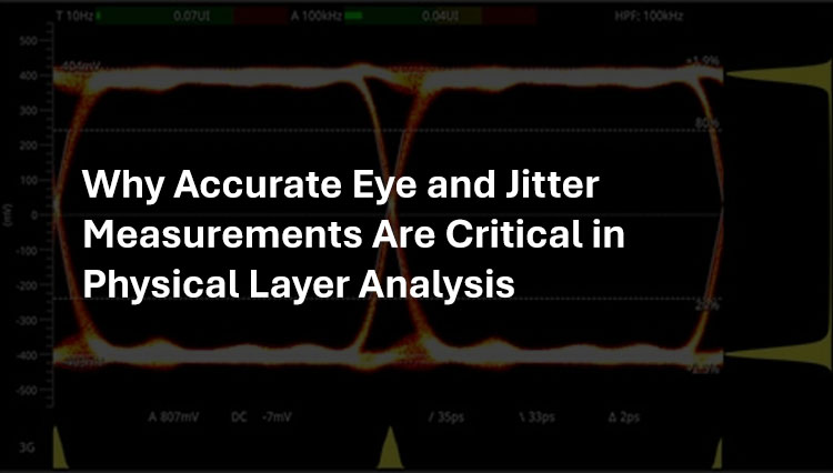
An eye diagram provides a visual method of assessing signal quality. It overlays multiple bits of a digital waveform over time, forming an “eye” pattern. The openness and symmetry of this eye help engineers determine how clearly a receiver can distinguish between logic highs and lows at the correct sampling point.
Eye analysis reveals key physical characteristics, such as:
- Amplitude degradation due to attenuation
- Intersymbol interference from poor equalization
- Timing shifts and signal reflections
- Rise and fall time violations
- Deformation due to cable or connector effects
The PHABRIX Qx Series offers real-time eye pattern visualization for a wide range of SDI rates, from HD up to 12G-SDI. Unlike general-purpose scopes, the Qx is specifically designed for the video and broadcast domain. It presents engineers with high-resolution eye diagrams, enhanced with overlays, histograms and real-time updates that help quickly identify signal degradation or marginal designs.
This is particularly useful during prototyping, as early design flaws are much easier and cheaper to resolve than problems that appear later in production.
Jitter Analysis: Timing Integrity Made Visible
While eye diagrams show the amplitude and shape of a signal, jitter measurements reveal variations in signal timing. Jitter describes how much a signal’s transition deviates from its ideal position. If bit edges drift too far from where they should be, the receiving hardware may sample incorrectly, leading to bit errors or complete link failures.
Jitter can be broken into different components:
- Random Jitter: Caused by thermal noise or other unpredictable sources
- Deterministic Jitter: Predictable patterns often caused by crosstalk, power supply interference or data-dependent transitions
- Total Jitter: The full range of variation, combining both Random Jitter and Deterministic Jitter
As data rates increase and bit periods shrink, even small amounts of jitter can cause major issues. For instance, at 12G-SDI rates, a single bit lasts less than 85 picoseconds, leaving very little margin for error.
The Qx Series provides detailed jitter analysis tools, including alignment and timing jitter histograms, crossing point plots, and tools to observe jitter trends over time. Engineers can isolate jitter components and understand their root causes, which is especially helpful when debugging clock domains, transmission paths or high-speed interfaces.
Debugging Development Hardware: Practical Use Cases
1. FPGA Transmitter Validation
An engineer is testing a custom SDI transmitter built into an FPGA. While it performs well under simulation, it occasionally fails in real hardware setups. Using the Qx’s eye diagram tool, the engineer observes a partially closed eye caused by excessive intersymbol interference. With this insight, they adjust the transmitter’s pre-emphasis and drive strength settings, restoring a clean signal. Jitter analysis further reveals that periodic timing noise is linked to a shared clock source, leading to improvements in power domain isolation.
2. Cable Qualification Testing
A team is evaluating new, lower-cost coaxial cables for use in a 6G-SDI video router. Initial results appear fine, but issues start to appear with longer runs in real installations. The Qx Series highlights that the new cable introduces a higher level of deterministic jitter that exceeds the system’s tolerance. This prompts a change in the supplier specification, avoiding widespread deployment issues.
3. Compliance Testing Prior to Release
Before releasing a new SDI-to-IP bridge product, a QA team uses the Qx platform to verify physical layer compliance against SMPTE standards. The eye diagram confirms sufficient margin at all supported rates, while the jitter tools confirm stable performance under stress. This provides a high level of assurance that the product will operate reliably across a wide range of field conditions and infrastructure types.
The Value of Early Physical Layer Insight
Addressing physical layer issues early in development pays significant dividends. It reduces the risk of late-stage failures, accelerates debugging and protects your product’s reputation for reliability. Without accurate tools, teams risk entering production with marginal designs that may fail unpredictably in the field.
Benefits of accurate eye and jitter measurements include:
- Faster fault isolation during prototyping
- Objective insight into signal margin and performance
- Verification of cable and connector choices
- Prevention of timing-related receiver errors
- Greater confidence during compliance and interoperability testing
The PHABRIX Qx Series: Built for the Broadcast Development Lab
The PHABRIX Qx Series is uniquely positioned to serve broadcast and video engineers. It combines traditional physical layer tools with an integrated platform for SDI, IP, HDR, metadata and audio analysis. For hybrid environments where SDI and ST 2110 co-exist, this all-in-one capability makes it ideal for both hardware developers and system integrators.
PHABRIX Qx Series hardware development features include:
- Eye pattern display up to 12G-SDI with histogram support
- Real-time jitter measurement with detailed analysis tools
- Full SDI status monitoring including cable length and CRC errors
- Built-in generator and analyzer tools for closed-loop testing
- Passive SDI monitoring for capturing real-world behaviour
By replacing multiple separate instruments with a single, video-centric platform, the Qx Series simplifies test workflows and reduces setup complexity. This makes it easier to catch errors, confirm compliance and move projects forward with confidence.
Conclusion: Build on a Solid Foundation
Physical layer integrity is the cornerstone of reliable hardware. With signal speeds and complexity increasing year after year, the importance of accurate, detailed eye and jitter measurement is only growing.
Whether you’re building a next-generation router, designing an ST 2110 gateway, or tuning a transmitter inside an FPGA, the PHABRIX Qx Series gives you the insight to do it right.