LV5900A
Waveform Monitor8K | 4K | 12G-SDI | 3G-SDI | HD-SDI | HDR
Compact instrument specifically designed for SDI video signals
Compact Waveform Monitor without sacrificing performance, supporting SDI signals up to 12G rates.
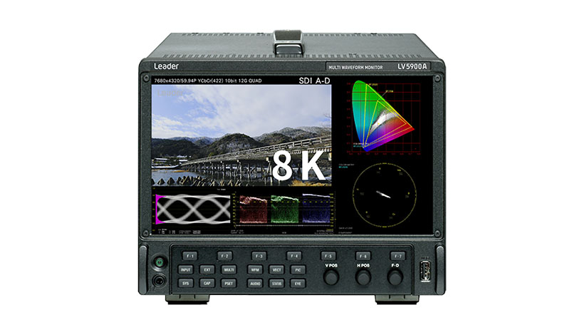
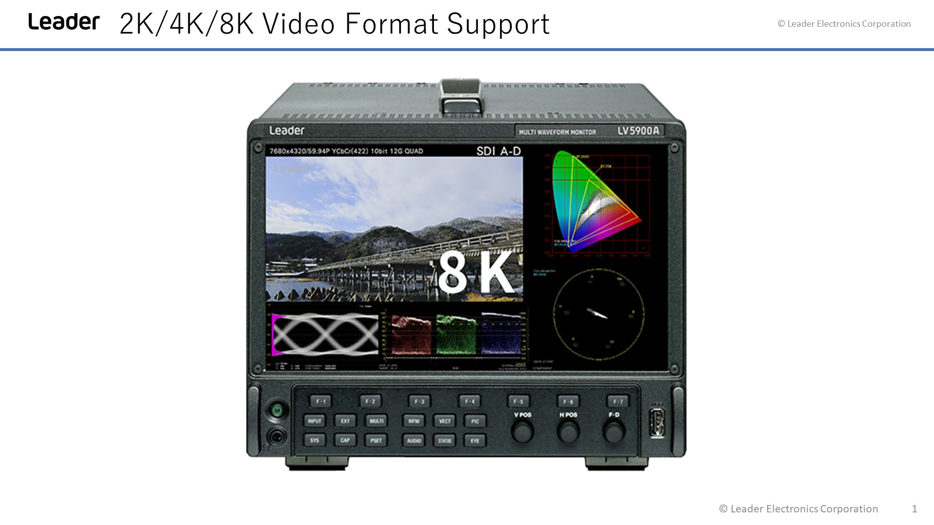
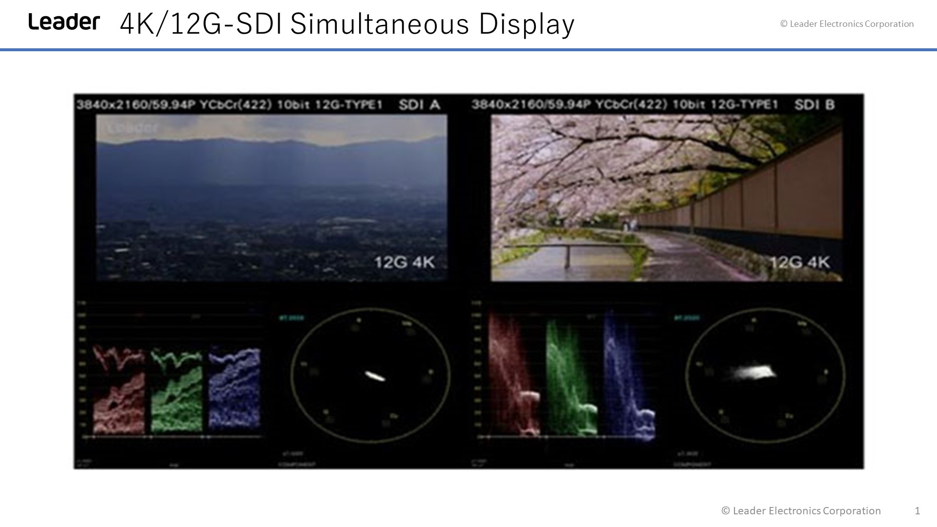
The LV5900A waveform monitor supports SMPTE ST 2082-12, which is used to receive 7680 (8192)×4320/59.94P YCBCR 10- bit 8K video via 12G-SDI QUAD LINK. As it supports not only 8K but also a 4K input and four simultaneous HD inputs, you can use it as a high-end 8K system and switch between other systems as needed. The waveform, vector, picture, and eye pattern displays allow for the measurement and quality control of various video signals. The status display allows you to view various error statuses and check on system stability by viewing event logs and long-term charts.
KEY FEATURES
2K/4K/8K Video Formats
Video formats support includes SDI signals in various formats ranging from, 8K video format with quad link of 12G-SDI, 4K video format with the single link of 12G-SDI, dual link of 6G-SDI, quad link of 3G-SDI and quad link of HD-SDI, in addition to the single link of HD-SDI and 3G-SDI.
8K Square Division
The LV5900A also supports 8K divided into 4K sized squares. While the 8K square division system is not included in the television signal standard, it is a system used when existing 4K equipment is repurposed to partially process the video signal in each area.
Customisable Layout
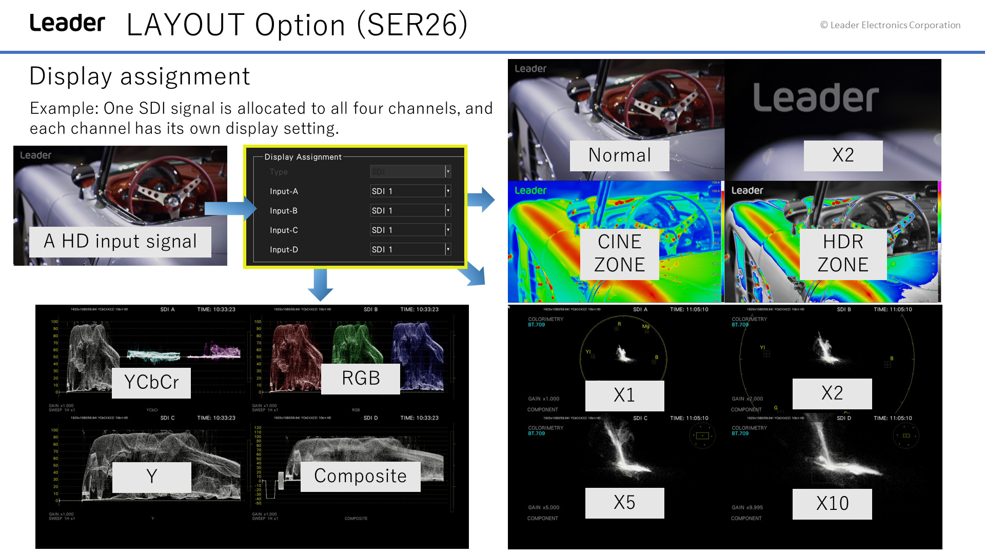
Various items such as video signal waveforms, vector waveforms, and pictures of input signals can be laid out in any position with your favorite size.
HDR Monitoring
In addition to HLG and PQ provided by ITU-R BT.2100, the level monitoring of the HDR signal corresponding to S-log3 and the level management at the assumed luminance (Nits) in a display considering OOTF are possible.
The video signal waveform displays HDR scale along with the IRE scale. In the cine zone display, the luminance distribution of the HDR area can be easily confirmed by displaying the SDR area in monochrome, and the HDR with a color according to the brightness.
Eye Pattern Display
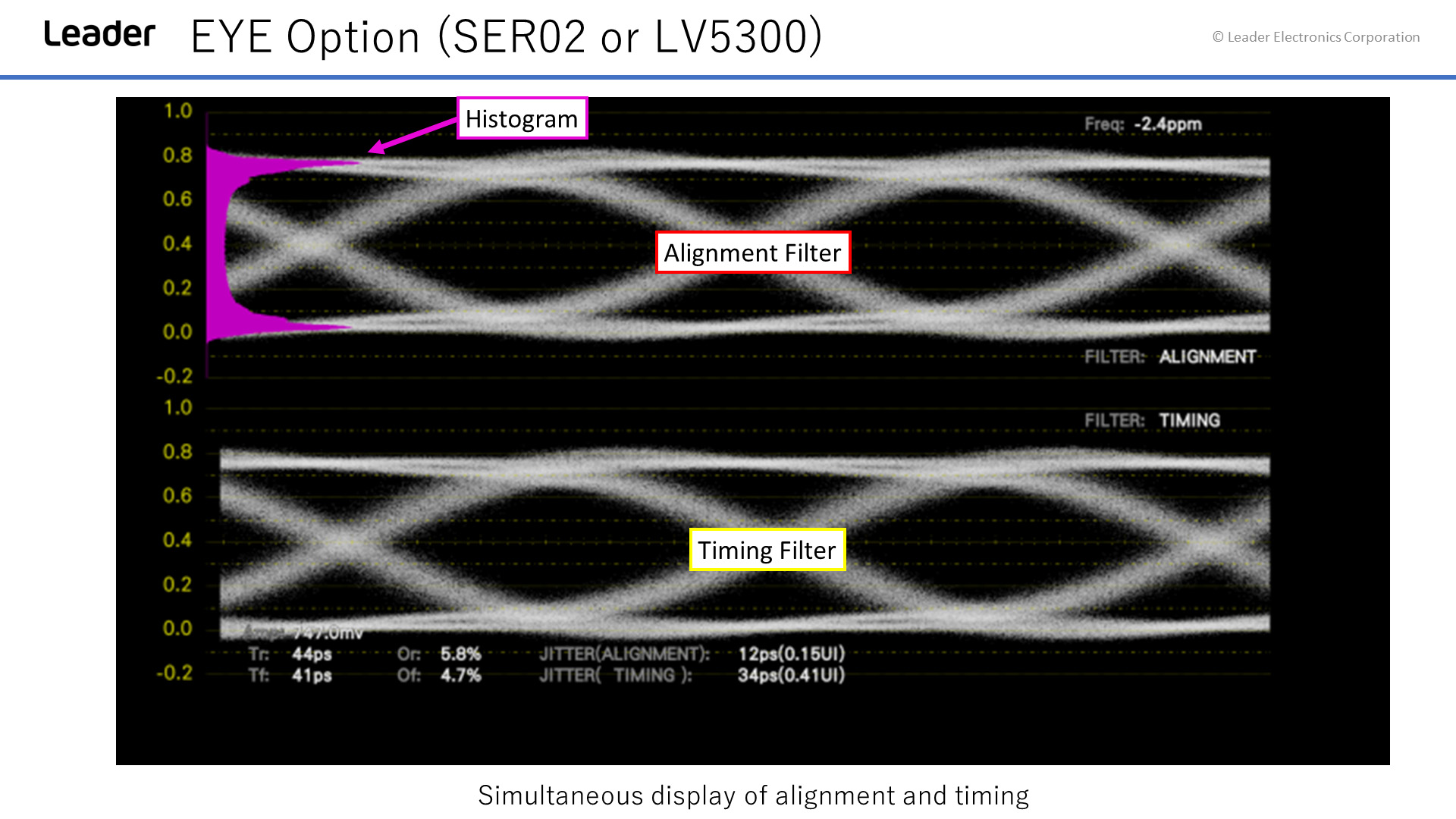
Both eye-pattern and jitter displays are available for SDI signals covering from HD-SDI through 12G-SDI. The LV5900A automatically calculates key eye measurement values. Furthermore, a histogram can be superimposed on the eye pattern display for more detailed physical layer evaluation.
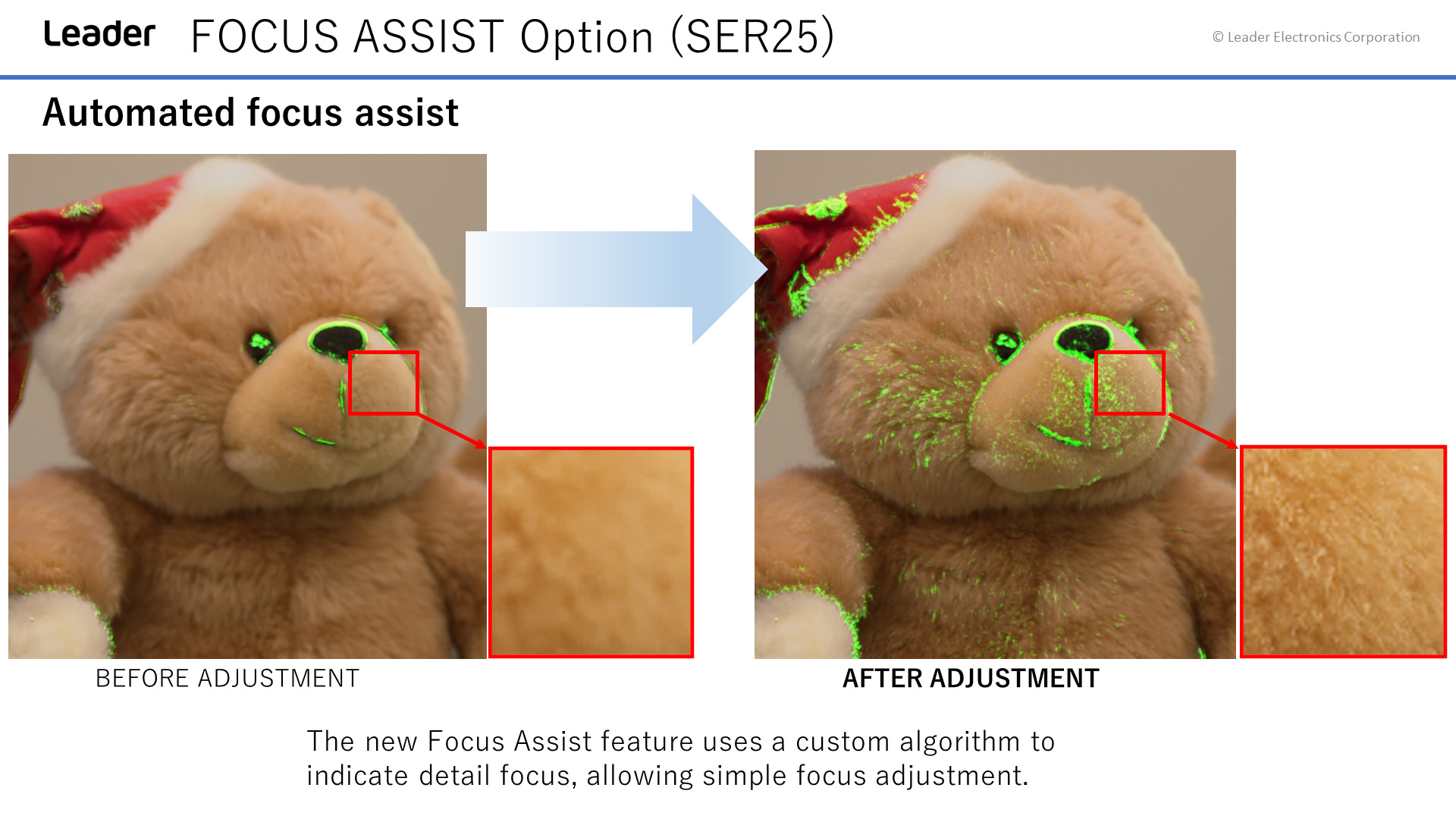
Focus Assist
This is a focus detection function realizing a new algorithm based on nonlinear super resolution technology. The focus details can be detected with high sensitivity even with low-contrast images, which were conventionally difficult to detect. In addition, sensitivity can be selected from 5 levels according to the video scene.
TOOLSETS
Standard Functionality
Waveform Monitor
 RGB
RGB
- Overlay: Overlays component signals
- Parade: Displays component signals side by side
- Blanking Interval: H and V blanking periods can be masked.
- Line Select: Displays the selected line
- Variable Gain:
Gain x1 ×0.2 to ×2.0
Gain x5 ×1.0 to ×10.0
Gain x10 ×2.0 to ×10.0
 Ycbcr
Ycbcr
- Overlay: Overlays component signals
- Parade: Displays component signals side by side
- Blanking Interval: H and V blanking periods can be masked.
- Line Select: Displays the selected line
- Variable Gain:
Gain x1 ×0.2 to ×2.0
Gain x5 ×1.0 to ×10.0
Gain x10 ×2.0 to ×10.0
 Composite
- Overlay: Overlays component signals
- Parade: Displays component signals side by side
- Blanking Interval: H and V blanking periods can be masked.
- Line Select: Displays the selected line
- Variable Gain:
Gain x1 ×0.2 to ×2.0
Gain x5 ×1.0 to ×10.0
Gain x10 ×2.0 to ×10.0
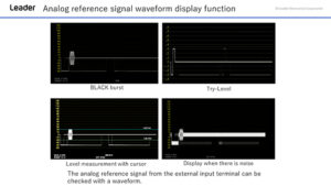 Analog Reference Signal
- Compatible SDI Systems Can be displayed for SD, HD, 3G-A, and 3G-B-DL
Vectorscope
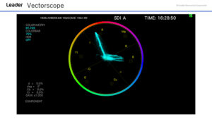 Vectorscope
- Gain: ×1, ×5, IQ-MAG
- Scale:
Type AUTO, ITU-R BT.601, ITU-R BT.709, DCI, ITU-R BT.2020
Color Bar Saturation 75 %, 100 %
IQ Axis Show or hide - Vector Marker Display
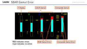
5BAR RGB GAMUT
- Function: Converts an SDI signal into Y, R, G, B, and composite values, and then displays the five peak levels.
- Error Level: Based on the gamut error, composite gamut error, and luminance error thresholds
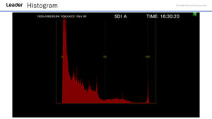 Histogram
- Histogram Display: Displays the Y, R, G and B histograms
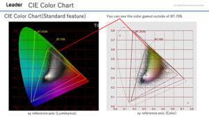 CIE Colour Chart
- Display Standard: CIE1931 (xy display), CIE1976 (u'v’ display)
- Display Type: Chromaticity diagram display, color temperature display
- Display Mode:
Chromaticity Diagram Display
Luminance display, color display - Color Temperature Display Luminance display:
Colorimetry ITU-R BT.601 (525), ITU-R BT.601 (625), BT.709, DCI, ITU-R
BT.2020
Picture
 Picture View
- Level Mapping: Maps the black level to 0 (8bit), SDI code value (when receiving 10 bit RGB) 1024 to 255 (8 bit)
- Display Sizes: Reduced, actual size, ×2 (4K not supported), full frame (4K not supported)
- Quality Adjustment and Color Selection:
Brightness, contrast, RGB gain, RGB bias, chroma gain,
monochrome display (RGB gain, RGB bias, chroma gain not valid)
 5BAR Gamut Error
- Error Indication: Displays markers in the gamut error and level error areas
 SCTE-104
-
- Function: SCTE-104 message monitoring
- Supported: Standard SMPTE 2010, ANSI/SCTE 104
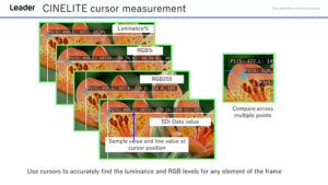 Cinelite
-
- Function: Video levels are displayed numerically.
- f Stop Display (not supported on the SER23):
Displays f Stop values relative to a reference point
Set in reference to an object with an 18% reflectance
f Stop gamma correction - HDR Display (SER23)
 Closed Caption Display
-
- Function: CEA-608, CEA-708 closed caption, Teletext, OP47 subtitle superimposed on SDI signal can be decoded and displayed.
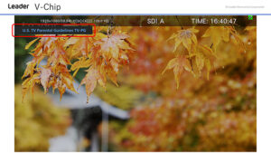
V-Chip
-
- V-Chip Display
Audio

Audio Bar Graph
Input Signal: SDI embedded audio
Digital audio I/O connector (SER03)
Analog audio input (SER03) SFP IP Audio (SER05/SER06)
Format: L-PCM, Dolby-E (SER04), Dolby Digital (SER04),Dolby Digital Plus (SER04)
Status
 Event Log
- Function: Records detected errors, events—such as the instrument
switching between input signals, and timestamps. - Log Capacity: Up to 1000 events
- Data Output Overwrite mode, Stop after 1,000 events
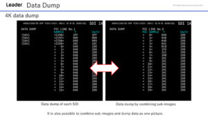
Data Dump
- Display Format: Displays serial data sequence or displays each color
component separately - Line Select: Displays the selected line
- Sample Select: Displays from the selected sample
- Jump Feature: Jumps to an EAV or SAV
- Data Output: Text output to USB memory

Phase & Timing Difference
- Function: Displays the phase difference between a reference signal and
an SDI signal numerically and graphically - Reference Signal: SDI / External sync signal, PTP (SER05/SER06) (*1)
RTP, External sync signal (BB), FPT (SER06) *1 Complies only with SMPTE ST 2110
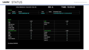 Status Indication
- Signal Detection
- Displays the video signal format
- Frequency Deviation Display (not displayed for IP signals)
- Equivalent Cable Length Display (not displayed for IP signals)
- Error Count Display
- Video Error Detection
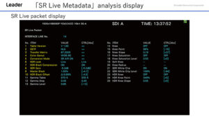
SR Live Packet Display
- SR Live Metadeta analysis display
HDR Measurement
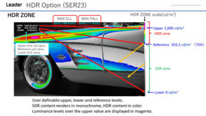
HDR Zone
- HDR zone display: The luminance distribution of the HDR area can be easily confirmed by coloring the SDR area with monochrome, and the HDR with a color according to the brightness.
- HDR point measurement: The crosshairs can be freely moved. Up to 3 points can be measured simultaneously
- Approved standard
ITU-R BT. 2100 (HLG, PQ), S-Log 3, C-Log, Log-C
It corresponds to all except SD input of SDI.

HDR Waveform
- HDR waveform display
- HDR point measurement:
The crosshairs can be freely moved.
Up to 3 points can be measured simultaneously - Approved standard
ITU-R BT. 2100 (HLG, PQ), S-Log 3, C-Log, Log-C
It corresponds to all except SD input of SDI.
SD, HD, 3G SDI Input and EYE Pattern Display
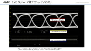
EYE Pattern Display
- The eye pattern waveform, jitter waveform of SDI signal, and the measurement result of each parameter can be displayed.
- Only BNC input 1 supports eye pattern display.
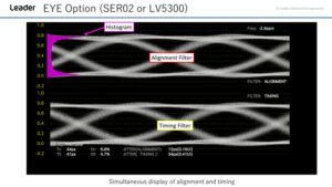
Dual Eye Pattern
- Simultaneous display of Alignment and Timing
SDI Generator Function

TSG Option
- Output pattern: 100% color bar, 75% color bar, HD multiformat color bar *1, 4K multiformat color bar *1, color raster, gamma, cross hatch, 10 step, limit lamp, check field, lip sync pattern(LV5600-SER03 is required), HDR color bar (LV5600-SER23 is required) *1
- Scrolling *2
Direction: Eight directions (up, down, left, right, and their combinations)
Speed: Range and Unit Per frame (field) 4 to 124 dots, in 4 dot steps - Moving Box *2 : ON / OFF
Colors: WHITE / YELLOW / CYAN / GREEN / MAGENTA / RED / BLUE / BLACK
Speed: 1 to 3 - Embedded Audio
*1 It cannot be set in horizontal 4096 and 2048 pixel format.
*2 Either scrolling, or moving box can be turned on.
Colorimetry Zone Display
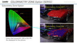
Colorimetry Zone
- This feature simplifies the task of identifying the reproduction errors which can occur when transmitting video content produced in BT.709, DCI-P3 or BT.2020 wide color gamut or when converting content from BT.2020 to narrow color gamut.
Focus Assist Function
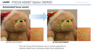
Automated Focus Assist
- This is a focus detection function realizing a new algorithm based on nonlinear super resolution technology.
- Sensitivity can be selected from 5 levels according to the video scene.

Focus Assist - Sensitive Mode
- Focus assist function in the dark
Customised Layout Function
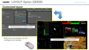
Customisable Layout
- Various items such as video signal waveforms display, vector display waveforms, and images of input signals can be laid out in any position with your user’s preferred size. Multiple input signals up to 4 inputs can be displayed simultaneously, or one input signal can be displayed on multiple screens.

Customisable Layout - Continued
- Swapping vector and audio

Display Assignment
- 1 SDI input signals of 1 to 4 input terminals can be allocated to A to D display channels.
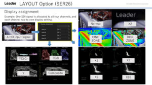
Display Assignment - Continued
- For example, displaying the signal input to SDI input 1 as component video waveform can be displayed on display channel A and the composite video waveform can be displayed on display channel B.
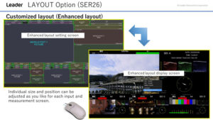
Enhanced Layout
- Enhanced layout is an extended function that enables the measurement screens of up to four
channels to be laid out on a single screen simultaneously in simul mode.
ID, Iris, TALLY Display Function
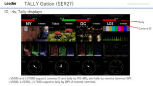
ID, Iris, Tally Displays
- Serial communication RS-422/485 terminals enable to display camera ID, and tally. Fast switching of tally display by remote terminal is also possible.
Extended Vectorscope Display

Extended Vectorscope
- RGB Vector and YCbCr Vector
Other
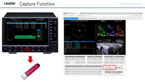 Capture Function
- Screen capture: A screen capture function to capture the display screen as still image data and a frame capture function to capture 16 frames of data are equipped.
- Frame capture: A frame Capture function to capture 16 frames of the SDI signals is equipped. There are two methods; one is to import them manually and another is to take them automatically when an error occurs.
* Only one frame is captured when an error occurs.
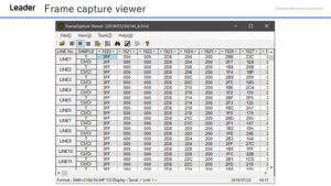 Frame Capture View
- Function: Search for data captured by the frame capture function, error search, and export to CSV are possible.
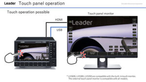 Touch Panel Operation
- Excellent operability: The LV5600 adopts a 7-inch full HD panel with a touch panel function.
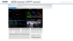 Web Browser
- Controlled remotely from a Web browser on a PC over an Ethernet connection, and used to perform automatic measurements using TELNET or FTP.
 Mouse Operation
- All operations are possible just by connecting the mouse.
READY TO TRANSFORM YOUR TEST & MEASUREMENT TOOLKIT?
Rear Panel I/O
ORDERING
Related accessories
| Product Name | Model | Remarks |
|---|---|---|
| RACKMOUNT ADAPTER | LR2490 | Dual rack mount adapter. |
| BLANK PANEL | LC2190 | Blank panel for the LR2490 |

